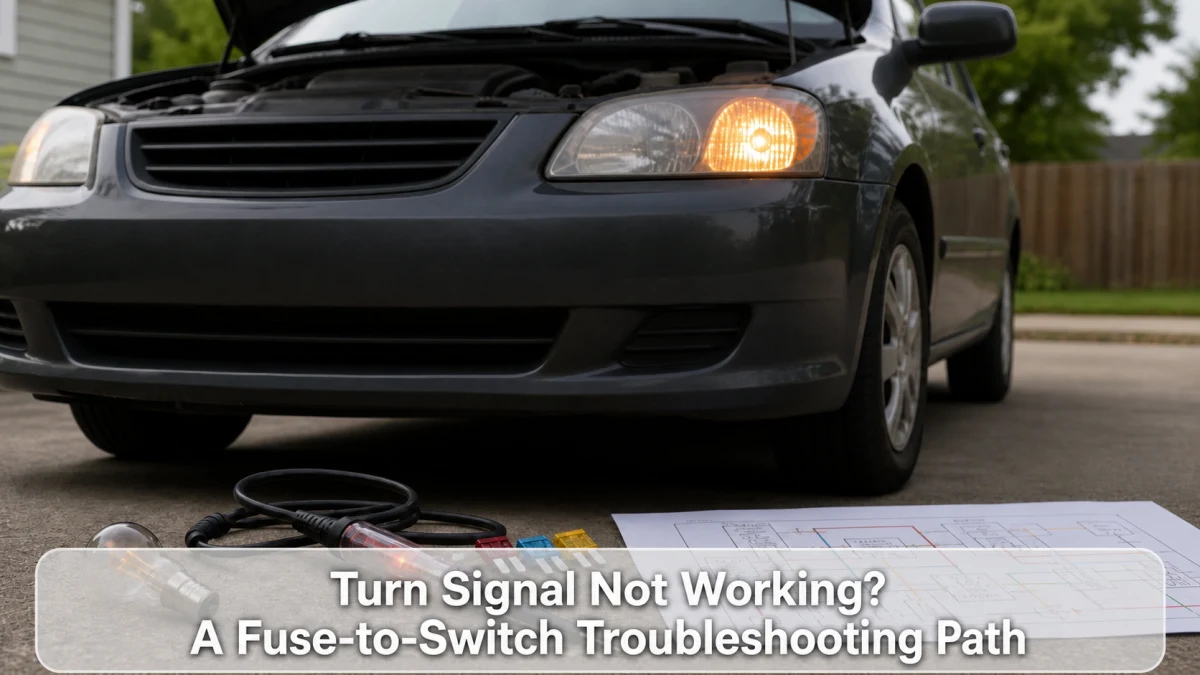
A turn signal that fails on one side points first toward bulbs or LEDs, sockets, grounds, wiring, or trailer connections on that side. When both sides fail but hazards work, the turn-signal switch or its command path becomes more relevant. Modern body-control systems require a wiring diagram and scan data before replacing a relay.
One-side versus both-side fault tree
| Observed pattern | Start checking | Important caveat |
|---|---|---|
| One lamp out on one side | Bulb/LED unit, socket, local ground and wire | LED lamp may be a complete assembly |
| Whole left or right side dead | Side circuit, connector, switch/module output | Compare hazards and scan command |
| Both directions dead; hazards work | Stalk switch input, ignition feed, body controller | Not every vehicle has a separate flasher relay |
| Signals and hazards both dead | Fuse, shared feed, hazard switch, module, ground | Test the actual circuit rather than guessing |
| Fast flash on one side | Failed lamp, high resistance, wrong bulb, trailer load | LED monitoring strategies vary |
| Indicator solid but lamps do not flash | Flasher/control fault, lamp load, switch, wiring | Older and modern systems differ |
Walk around the vehicle
With the vehicle safely parked, inspect every lamp while another person operates the controls, or use reflections without standing in traffic. Check front, rear, fender, and mirror repeaters. Note brightness differences and whether brake or tail lamps glow incorrectly; a shared ground fault can feed current through another filament.
Do not stare closely into a high-output LED. Allow incandescent bulbs to cool before handling, and use the exact bulb type and wattage.
Record whether the problem began after a bulb change, collision repair, trailer hookup, or heavy rain. Recent work and moisture often narrow the first inspection area without proving the cause.
Understand fast flashing
Traditional flashers change rate when circuit load drops after a bulb failure. A modern body controller may imitate that warning electronically. Installing low-current LED replacements without approved compatibility can trigger hyperflash, warnings, dim glow, or heat from added resistors. Restore the specified lamp before modifying the circuit.
Compare the hazard lights
Hazards may share lamps and wiring while using different switch inputs or control logic. If the failed side illuminates correctly with hazards, the lamp and some wiring can work, but that does not clear every connector or intermittent ground. If hazards also fail, look for shared feed, ground, module, or hazard-switch issues in the diagram.
Fuse, socket, and ground checks
- Identify the correct lighting fuse from current service information.
- Test it electrically on both sides. Replace only with the same rating.
- Inspect the lamp and socket for heat, corrosion, water, bent terminals, and wrong part fit.
- Measure voltage and ground under load; an open-circuit meter reading can hide resistance.
- Follow the harness for impact, trailer-splice, or prior repair damage.
- Clear water intrusion and repair terminals with approved parts.
If a fuse opens again, stop replacing it and locate the short. Never use foil or a larger fuse.
Trailer wiring is a frequent clue
Corroded trailer connectors, pinched harnesses, failed converters, and non-sealed splices can disable or backfeed vehicle lights. Disconnect the trailer and any removable adapter, then retest. Inspect the socket for moisture and bent pins. A tow-module code may provide the fastest direction on equipped vehicles.
Switch, relay, and body-control diagnosis
Older vehicles may use a replaceable thermal or electronic flasher. Newer vehicles often create the flash inside a body module and use the stalk as a low-current input. Listen for a click only as a clue—the dashboard speaker can generate it. Scan the body module for switch input, lamp command, codes, and current-monitoring status.
Steering-column trim can sit beside airbag components and clock-spring wiring. Do not disassemble it without the restraint-system disable procedure and required waiting time. Qualified service is appropriate when switch testing requires column access.
When other dashboard lights also fail
A shared ignition feed, dimmer, body module, network, or ground issue may affect multiple functions. Preserve all body and cluster codes before disconnecting the battery.
Keep reflective markers and a flashlight from the roadside emergency checklist, but hand signals or hazard equipment are not a permanent substitute for required turn lamps.
Frequently asked questions
Can a fuse affect only one turn signal?
Some circuits have separate protected outputs, while others share a fuse. The fuse layout and wiring diagram for the exact vehicle decide.
Why does the signal work in warm weather only?
Temperature can change terminal contact, solder joints, switch resistance, moisture, or an electronic component. Test voltage and command while the fault is present.
Can I replace an incandescent bulb with any LED?
No. Fit, polarity, light distribution, load monitoring, legal approval, and heat management matter. Use a vehicle-approved replacement.
Sources
- Ford owner’s manual: direction indicator operation example
- AutoZone: turn-signal switch and fault overview
Bottom line: compare one side, both sides, and hazards before buying parts. The lamp pattern and body-control data show whether to stay at the bulb and ground or move toward the switch and controller.