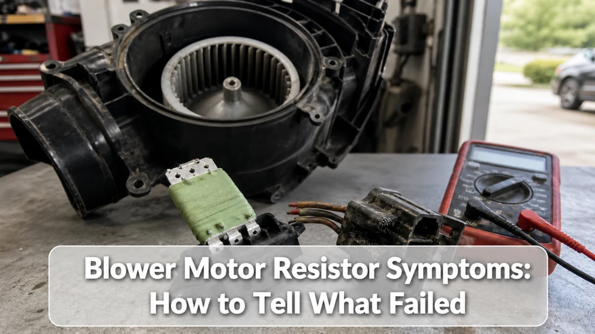
A failed blower motor resistor often removes one or more fixed fan speeds while leaving another speed working. However, a bad motor, overheated connector, fuse, relay, switch, wiring fault, or electronic control module can create a similar complaint. Use the speed pattern and circuit tests before replacing parts.
What the blower resistor actually does
In a conventional stepped-speed circuit, current passes through different resistance paths to reduce blower-motor speed. High speed may bypass part or all of the resistor. That is why “high works, lower speeds do not” is a classic resistor pattern.
Many newer vehicles use a solid-state blower control module and pulse-width control rather than a simple coil resistor. Automatic climate control can also involve sensors, a control head, and network commands. Identify the installed system before applying a generic test.
Fan-speed failure pattern matrix
| Fan behavior | More likely areas | Important counter-check |
|---|---|---|
| High works; several lower speeds do not | Resistor paths, connector, switch contacts | Check motor current and connector heat |
| Only one intermediate speed is missing | One resistor path, switch, or wiring | Use the exact circuit diagram |
| No speeds work | Fuse, relay, power, ground, motor, control module | Do not assume the resistor is open |
| Fan runs only after hitting the dash | Worn motor brushes or loose connection | Test at the motor connector without striking components |
| Fan speed changes by itself | Electronic module, control signal, connector, motor load | Scan HVAC codes and commands |
| Airflow is weak at every speed | Filter restriction, evaporator debris, duct issue, motor | Separate speed sound from actual airflow |
Resistor versus motor versus air-door problem
A resistor affects the blower’s electrical speed. A blend or mode door changes temperature or outlet location, not whether the fan motor spins. If the motor sound changes normally but air comes from the defroster instead of the face vents, diagnose the air-distribution system.
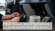
A motor can stop on one worn commutator segment, draw excessive current, squeal, scrape, or start intermittently. Excess motor current creates heat at the resistor and connector, so replacing only the visibly burned resistor can lead to another failure. Compare the symptoms with a complete blower motor test before choosing parts.
Safe test sequence
- Turn the ignition and climate system off. Locate the correct fuse information in the manual or service data.
- Test every speed and mode. Record whether the AC indicator, compressor request, and outlet selection work.
- Scan the HVAC module where supported. A body or HVAC code may not appear on a basic engine-code reader.
- Disconnect power as the service procedure requires before unplugging the resistor or module.
- Inspect terminals for melting, looseness, corrosion, and discoloration. Repair a damaged connector with the approved method.
- Using the correct wiring diagram, verify supply voltage, ground integrity, and the speed-control signal under load.
- Check blower-motor current against model data and make sure the wheel turns freely with power safely isolated.
Do not probe yellow airbag wiring or nearby supplemental-restraint connectors. Avoid spreading terminals with oversized meter probes. Back-probing and load testing methods must match the connector and service instructions.
Can resistance be checked on the bench?
A conventional resistor assembly may have measurable continuity across specified terminals, but pin positions and expected values vary. A thermal fuse can be part of the assembly. Solid-state modules cannot be judged with the same simple resistance logic. Consult the wiring diagram and component test for the exact vehicle.
Continuity alone also misses a terminal that fails under current. Voltage-drop testing under load can reveal resistance in a connector, ground, relay, or wire that looks acceptable with the circuit off.
Why the connector melts
Loose terminal tension produces resistance and heat. Excessive motor current, moisture, repeated thermal cycling, or a poor prior repair adds stress. Replace or repair all damaged terminals and address the cause. Twisting wires together or installing an underrated generic connector is not a durable repair.
Repair decision
Replace a resistor or control module after the circuit proves that it receives correct power, ground, and command but does not provide the specified output. If the connector is heat-damaged, use the manufacturer-approved pigtail or terminal repair. Test the blower motor and cabin-air path so the new component is not overloaded.
If airflow exists but the cabin will not cool, continue with the AC not blowing cold diagnostic sequence; the speed controller may not be the cause.
Frequently asked questions
Will a bad resistor stop the blower completely?
It can on some circuits, especially when a shared thermal fuse or electronic module fails, but a complete no-blower condition also requires fuse, relay, motor, power, ground, and command checks.
Why does only high speed work?
High speed often uses a bypass path, allowing it to work after lower-speed resistor paths fail. That pattern is useful evidence, not universal proof.
Can I bypass the resistor?
Do not install a permanent bypass. It can defeat circuit protection or control and overload wiring. Use only a documented test method for the exact circuit.
Sources
- NHTSA-hosted service bulletin: vehicle-specific blower resistor diagnosis example
- CarParts: blower motor resistor test overview
Bottom line: missing lower speeds strongly suggests the resistor circuit, but motor load and connector condition matter. Test the entire path before installing a replacement.